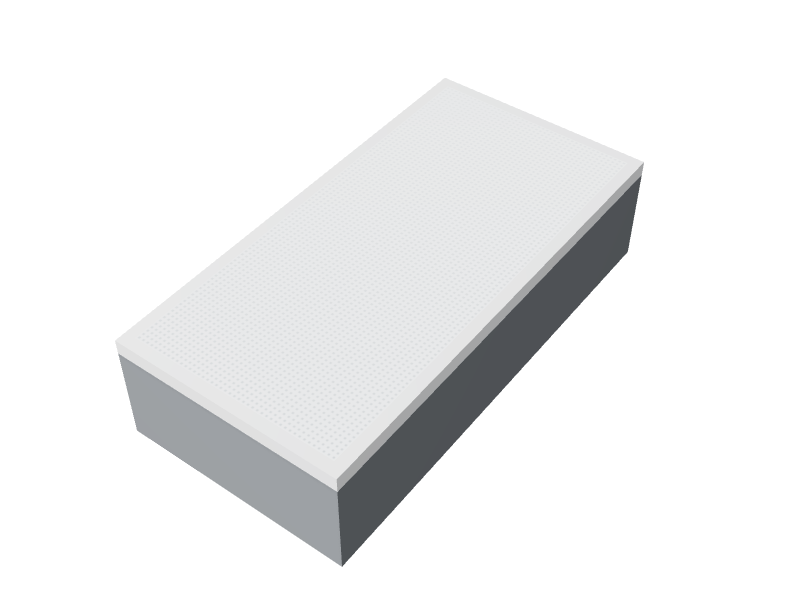
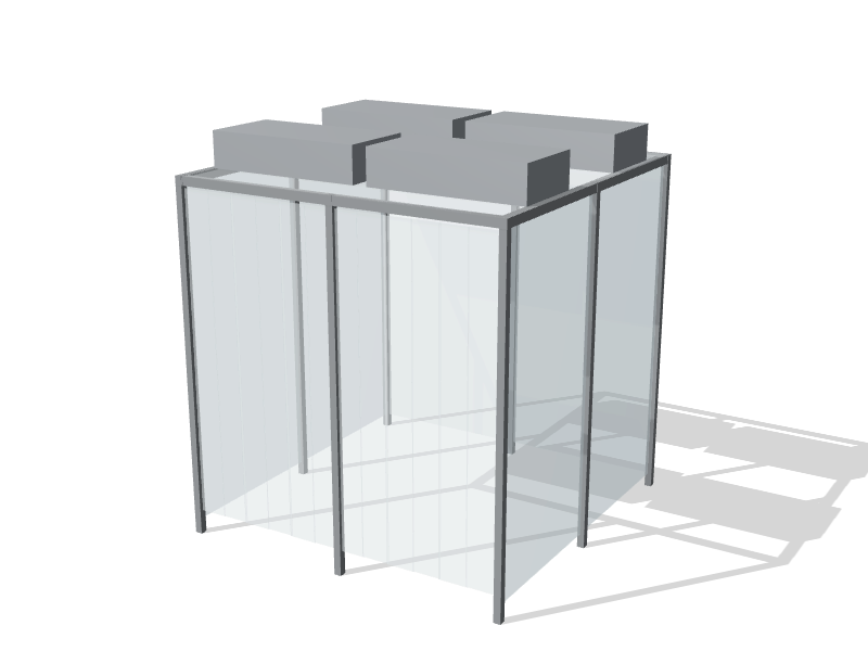
A fan filter unit, or FFU, combines a fan and a HEPA filter in one module that drops into a ceiling grid. It draws air from the plenum above the ceiling and pushes it down through the filter into the room. FFUs became the default for modular cleanrooms because they spread fan power across the ceiling, let a room grow one module at a time, and replace much of the ductwork that a central system would need.
How an FFU works
Each unit has four main parts:
- Housing. Painted steel, aluminum or stainless, with an inlet on top and a sealed edge that sits in the grid.
- Fan and motor. Most current units use EC (electronically commutated) motors, which are efficient across a wide speed range and can be controlled and monitored individually.
- Filter. A HEPA filter, commonly H14 under EN 1822, which captures at least 99.995% of particles at the most penetrating particle size. ISO 4 and cleaner rooms may use ULPA filters instead.
- Prefilter. A coarse filter on the inlet catches larger debris and extends HEPA life.
Common nominal sizes are 600 × 1200 mm (2 × 4 ft) and 600 × 600 mm (2 × 2 ft). In unidirectional zones, FFUs typically run at a filter face velocity around 0.45 m/s (90 fpm). Non-unidirectional rooms often run them slower, which saves energy and reduces noise.
FFUs recirculate room air. They do not heat, cool, dehumidify or bring in outdoor air. A separate air handler supplies conditioned make-up air to the plenum, sets the room pressure and removes heat, including the heat the FFU motors add. The HVAC and air change guide covers how the two systems work together.
Ceiling coverage by class
Coverage is the share of the ceiling occupied by filter area. It is a design rule of thumb, not a requirement of ISO 14644-1, and published ranges vary. Common starting points are:
| ISO class | Typical filter coverage of ceiling | Usual airflow pattern |
|---|---|---|
| ISO 5 | 60 to 100% | Unidirectional over the critical zone |
| ISO 6 | 25 to 40% | Non-unidirectional, high air change |
| ISO 7 | 15 to 25% | Non-unidirectional |
| ISO 8 | 5 to 15% | Non-unidirectional |
The right figure depends on how many people work in the room, the particles and heat the process generates, the ceiling height, the fan speed setting and where the returns are. The HVAC engineer sets the final count. The lab planner uses a starting value inside each range so you can see a first estimate of filter count and ceiling layout.
A quick check shows how the arithmetic works. A 30 m² (about 320 sq ft) ISO 7 room at 18% coverage needs about 5.4 m² of filter area. A nominal 600 × 1200 mm unit occupies 0.72 m² of ceiling, so that is roughly eight FFUs before the engineer adjusts for real loads. Do the same sum for ISO 5 and the count rises several times over, which is why ISO 5 is normally limited to the zones that need it.
Choosing and specifying FFUs
- Speed control and monitoring. EC units can be grouped and controlled from a central panel or the building automation system, with alarms for fan failure. In a validated room, any reduced-speed setback mode must be defined, tested and documented, and room pressure must hold in every mode.
- Filter leak testing. Installed HEPA filters are leak-tested by challenging them with aerosol and scanning the face. Ask whether the unit has an upstream aerosol injection port and an upstream sampling port, and whether the filter can be scanned without removing anything.
- Room-side replacement. Room-side replaceable filters avoid lifting units out of the grid, but they add a frame on the room face. Plenum-side replacement needs access from above.
- Seal to the grid. Gasketed units suit standard grids. Gel-seal units, with a knife edge set into a gel-filled channel, give a more reliable seal and are common in ISO 5 and cleaner ceilings.
- Noise. Dozens of units add up. Ask for sound data at the speed you will run, not at maximum.
- Weight and seismic restraint. The grid must carry the FFUs, lights and anything else hung from it. In seismic regions such as coastal British Columbia and parts of Quebec, specify seismic restraint for the grid and units.
- Lighting. At high coverage there may be no free modules for flat panels, so teardrop lights on the T-bar are the usual answer.
Questions to ask your supplier
- What filter class is fitted, and is a factory test report supplied with each filter?
- What airflow and power draw does the unit deliver at our planned speed, with the filter at its initial resistance?
- Is the unit EC-driven, and how does it report faults?
- Can the filter be leak-tested in place and replaced from the room side?
- What sealing method does the unit use, and which grid does it require?
- What sound level should we expect at our planned speed?
FFUs also power free-standing enclosures; our guide to softwall and hardwall cleanrooms compares that approach with a built room.